|
Cheltenham Society of Model Engineers |
Next Public Afternoon (1330 - 1600hrs) |
|
|---|---|---|
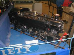
| GWR 1500 Class Project |   |
| Home | The Society | Calendars | Galleries | Projects | Attic | Links |
|---|
However, an advert on the 7.25"G Society website has paid dividends. Contacts made via the website have supplied me with Wheel Castings at a price substantially below that required by our normal model suppliers. Unfortunately, several of the castings that I have already purchased could have been supplied by the same contacts at a substantially lower price than what I'd paid! It does show the advantages that can be gained by joining a group of fellow enthusiasts. In addition, Polly Model Engineering produce a number of Lost Wax castings for their locomotives which are the same as those required by 'Paddington' and are at prices substantially below the prices charged by other suppliers, i.e. Brake Hangar Brackets £42 (£177), Brake Hangars £66 (£260), Brake Blocks £42 (£184), Brake Shaft Split Inner Bearing and Inside Weightshaft Split Bearing (same casting) £12 (£72). When I first started 'Paddington' I noticed that many dimensions on Sheet 1 of the drawing pack were specifically marked as "Use dimension marked DO NOT scale drawing". I naively thought that this meant that someone had 'proved' the drawings and there should be few problems. How I was wrong. I have listed below the concerns that I have with areas of the 'Paddington' drawings so hopefully others can perhaps be better prepared than me. Please take my comments for what they are, they are MY comments. Please feel free to e-mail me if you would like to comment on any of them (or warn me of any I've yet to find). As I have found the dimensions of many piece parts to be suspect I have taken to redrawing them with CAD before cutting metal. This has enabled me to build up a 'library' of parts and 'assemble' them on paper in order to give more confidence that the parts will go together. I now have a very effective CAD General Arrangement drawing. This CAD work has worked especially well with the valve gear. From my CAD drawings I estimate that the maximum cut-off in forward gear is 75.6% and in reverse gear is 77.0%. Don't know whether these are a little low for an engine that was designed to pull empty stock out of Paddington. My CAD work has even given me new drawings for the frames, but I don't think I'll get a new pair laser cut.
Work continues........
|
|---|

| Hatherley Lane, Cheltenham, Glos, GL51 6PN, UK | cheltsocietymodelclub@gmail.com | Tel: TBD | Legal Notices |
|---|
| Home | The Society | Calendars | Galleries | Projects | Attic | Links |
|---|