|
Cheltenham Society of Model Engineers |
Next Public Afternoon (1330 - 1600hrs) |
|
|---|---|---|
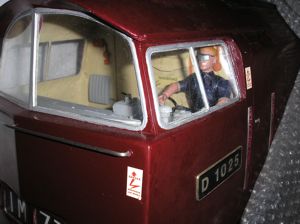
| Class 52 Project |   |
| Home | The Society | Calendars | Galleries | Projects | Attic | Links |
|---|
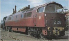
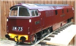
It was during a Public Running Afternoon in September 1999 that I decided that I would build a Diesel outline locomotive. What we need (I thought) is something different, something that will appeal to the younger visitors and something that I could have running by next season. A diesel seemed the answer - relatively uncomplicated (therefore, easy and quick to build), clean, and with no weight problems - cus it breaks down into several manageable parts.
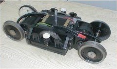
I purchased the drawings. However, they were basically only details for the powered bogies; there was very little information on the chassis/front end and next to nothing on the bodywork. However, there are two 'Western' Class diesels preserved at Bridgnorth on the Severn Valley Railway so getting pictures was not a problem. The first bogie was completed in about 80 man-hours. No difficulties were found other than the usual 'lack of meat' on some of the castings, although allowances could be made and excess metal left on other items to compensate. However, one unfortunate 'problem' did appear. The bogies have six wheels with a main casting carrying the centre, non-powered axle. This axle has sprung axleboxes to keep the wheels in contact with the rails.
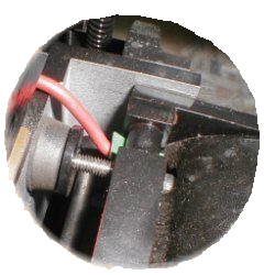
Rotating the motor or turning the motor assembly made no difference. My only option was to reduce the size of the suspension crossbar in the vicinity of the connection in order to allow the electrical connections to be made. With regard to the electrical connections, I do have some doubt. I question whether the push-on motor connectors are adequate for passing 10/15 Amps with negligible volt drop. A good soldered joint is the obvious answer but to do this means butchering the motor end caps to allow the wiring to pass through - something one doesn't really want to do on �40 motors. Advice states that the connectors are OK - but I remain sceptical.
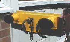
Each end of the casting has the offset on opposite sides so that the 'driven' wheels on each axle are on opposite sides of the bogie. If the offsets were reversed, the motors would have to be rotated 90� to realign with their mounting holes. This would move the connection terminals away from any obstruction. A quick referral to the drawings showed that I had machined them correctly (or at least as per the drawing). The drawing view was upside down. The only view was from the bottom - it should have been the view from the top. The aluminium buffer beams had been cast with tapered buffer stocks in-situ. The appearance of these is not prototypical and, therefore, not acceptable. The complete removal of the stock was contemplated but the fixing of any separate stock would be difficult due to the cast webbing on the rear of the beam. An external cutter was used to cut the outside of the buffer stocks into a parallel shank. Mild Steel rings were machined, with the correct outside profile, and loctited over the remaining aluminium 'stumps'. Small amounts of body filler were then used to put fillets in the corners etc. Hey Presto - correct looking buffer stocks.
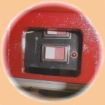
Using the computer X/Y co-ordinates were measured to generate the required shape. X/Y co-ordinates were also calculated for generating the front/rear face radius. Mild Steel bar was turned to produce the buffer shank and a round head complete with the front and rear face radii. Using a Dividing Head on the Milling Machine one quarter of the buffer head shape was machined using the X/Y co-ordinate data. This was repeated for the other three-quarters and for the other three buffer heads - a very time consuming exercise not recommended if making oval buffer heads for a living. The 'steps' around the periphery of the head were then blended in. All in all the manufacture of these was a very satisfying task. I wanted this locomotive to be as safe as possible for all potential users. Advice was sort from other society members and I purchased a '4QD' NCC35-24 controller, which has many built-in safety features. The unit has electronic ramping which only allows the locomotive speed to ramp up (or down) at a predetermined rate (user set). Also, if the locomotive is moving forward and the driver throws the reversing switch (which someone is bound to try), the speed will ramp down to zero before ramping up in the opposite direction. In addition, the hand controller will contain a "dead man's throttle", so that if released (by the driver dying or, perhaps, the locomotive breaking away from the train) the locomotive will decelerate to a halt. The controller also has regenerative braking, which passes all energy generated during locomotive braking back into the batteries. The only 'safety' feature lacking is that of the speed controller failing 'short circuit', when the locomotive would continue at full speed until the batteries became exhausted. I covered this situation by fitting a high current relay, controlled by a light action toggle switch, in the wiring link between the two 12V batteries (it's a 24V system).
The speed controller came ready assembled in an aluminium case and this has been fitted below the chassis in space directly between the left and right hand brake boxes. This has made the space inside the body available for other things. Two 42 Ampere Hour Deep Discharge batteries fit neatly within the chassis. Hanging brackets were made and fitted, as at 15kg each I felt it best to keep the batteries as low as possible.
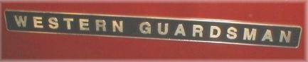
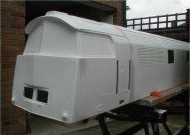
Much filler was put on, and much was rubbed off with abundant amounts of 'wet & dry' and water being used. Two coats of primer along with coats of BR Maroon - it really looked a Western. The final remaining item required to complete the bodywork (except for those 'rivet counting' details) was the transfer that locates on the side of the cab that doesn't carry a number plate (Westerns only carried one number plate on each end of the locomotive). However, this was not one of the many 'standard' transfers available from most Model Engineering Suppliers. Luckily I found the name of a specialist transfer company - Cambridge Custom Transfers - and they produced just what was needed (I'm not sure whether they still produce them). The 'Western' was wired with the two 12V motors in each bogie wired in series, with the two bogies being wired in parallel across the speed controller. This gave the diesel a top speed of about 5mph which dropped to about 3.5mph when pulling about four adults on the 1:120 incline on the Society track. Whilst corresponding with another model engineer, who had also built a 'Western', it was found that his diesel had a top speed of 9mph with a load of 12 adults! This was with a gear ratio of 9:1, whereas my 'Western' had a ratio of 7.2:1. It transpired that he was running all his 12V motors in parallel across the 24V. The 'Western' has now been re-wired to put the four 12V motors in parallel across the 24V controller. This has been tried on the Society track and has made a world of difference. The 'Western' pulled six adults plus myself around the track at a top speed of 10.5mph (at that speed it was most definitely not boring). At worst the controller was taking 40Amps. This value will have to be watched as the controller originally purchased is only rated at 35Amps (Hot)/50Amps (Cold). With the present performance the 70Amp controller would be preferable. This higher rated controller should be able to supply all the power demanded by the 'Western' in its new configuration. Trials of the locomotive on the track have taught me two things. Driving a steam engine with the constant attention required is good fun and really keeps you on your toes. However, driving a diesel can be a bit boring - because there is little to do and more especially because there is no noise, no audible feedback - it is dead silent. What it needs is a diesel horn and, more importantly, simulated engine noise.
At least for now, the project is complete. |
|---|

| Hatherley Lane, Cheltenham, Glos, GL51 6PN, UK | cheltsocietymodelclub@gmail.com | Tel: TBD | Legal Notices |
|---|
| Home | The Society | Calendars | Galleries | Projects | Attic | Links |
|---|