 |
Cheltenham Society
of Model Engineers |
Next Public Afternoon
(1330 - 1600hrs) |
|
| Class 08 Project |
  |
Class 08 Diesel
by Barry Leach |
 |
This was my first project in 7.25"G.
Until then I had always been an 'elevated track' buff. It was only after
running my 'Western' diesel on the ground (so to speak) at a Hereford
SME rally that I really appreciated what fun could be had with 'real railroading'.
I was hooked and wanted to have my own 7.25"G locomotive as soon
as possible.
At the 2002 Southern Federation Rally at Hereford, I had seen a Class
08 Diesel that was owned by a member of the Bridgend SME, and this had
really taken my fancy. It could be moved around in the back of a car,
plenty of power and should not take too long to construct. It was based
on the model sold by Compass
House Engineering with modifications to its basic appearance. I
decided to follow a similar path. |
 |
'Compass House' primarily sell the Class 08 as a 'ready to run' model but
they will sell the individual castings/parts (at least they did when I bought mine). However, they do not supply
any drawings.
I looked at their list of parts and decided to buy from them the following:
-
Motors and Motor Mounting Plates
-
Gears and Oilite Bearings
-
Wheel Castings
- Frames (0.25" thick Mild Steel flame cut)
-
Axles (to give me some idea for size
etc. for making the frame assembly)
- Dummy Leaf Spring Castings
- Axle boxes (they use a high grade plastic material)
-
Top Plate (48" x 14" x 0.187"
Mild Steel - I had no idea how I would purchase/handle this so I thought
it best to buy it finished)
-
Fibreglass Body Moulding
Everything else was to be made from raw
material with dimensions taken from photographs and/or the real thing. The 7.25"Gauge
Society handbook was also consulted and this gave me basic gauge dimensions
and buffer height etc. Drawings would be produced of all the parts made (that
was the intention anyway).
I collected all the purchased parts from 'Compass House' and at the same time
took the opportunity to see a finished model and measure the wheels for diameter/thickness
etc. It was obvious from the finished model that it is made as a production
'ready-to-run' model. The frames were 'spot welded' to the underside of the
top plate and the wheels drilled and pinned to the axle with a pin through the
wheel boss and axle. All of this made for quick production but poor maintainability.
The purchased axles had a wheel 'back-to-back' dimension of 6.750" whereas
the 7.25"Gauge Society recommend a dimension of 6.8125" for standard
gauge prototypes. Also, I felt the finish on the part of the axle that was to
run in the axle box was very rough. I decided to make new axles with the recommended
back-to-back dimension, proper keyways for keying the wheels and a polished
finish for running in the axle boxes.
|
I measured the thickness of the wheel
tread whilst at 'Compass House' but this didn't give me any idea of the
thickness of the wheel boss. I decided to leave an extra 0.062"on
the wheel boss thickness. With the 'back-to-back' wheel dimension, wheel
boss thickness, total axle box thickness and a small allowance for end
float this gave me a dimension of 9.125" between the frames. This
dimension conveniently allowed 0.25" shafts on the buffers to pass
into the space between the frames, and allow for a retaining washer on
the end.
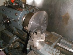
The wheel castings were very nice and some of the
best iron castings I have ever had the pleasure to machine.
|
Photographs showed that standard BR Buffer
Stocks could be used and that these should be mounted towards the bottom of
the buffer beam (this was measured as 3" wide plate from the size at the
end of the frames). The 7.25"Gauge Society handbook gave the dimension
between the buffer heads and the height of the buffers above the rail height.
These dimensions allowed the position of the axle box in the horns to be calculated.
The width of the top
plate was questioned. It was somewhat wider than the fibreglass body,
whereas photographs showed that the footplate was no wider than the body.
I've decided that the top plate needed to be reduced by 0.187" on
each side, giving a finished width of 13.625" as against the original
14". It was also narrowed further at the front. The Buffer Stock
position was assessed by known dimensions and photographs. From the photographs
it can be seen that the front buffer beam is only a little bit wider than
the outside of the buffer stocks. The front section of the top plate was
narrowed to the same width as the front buffer beam 10.688". This
gave an area for the large steps that are fitted at the front.
|
|
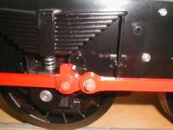
The original axles seemed to be a little long. With the dimensions used
between the frames, the supplied axlebox material and using 0.5" plate
for the cranks, there seemed to be about a 0.375" gap between the outer
axlebox face and the cranks. This did not look prototypical, so the length
of the axles was reduced by 0.3125" on each end. This gave a gap of about
0.0625" between the outside face of the axlebox and the crank and this
looked about right.
Adding a crank pin onto the cranks plus a retainer gave a clearance
of about 0.125" from the outside of the motion to the outside of the running
board. Again, this looked and seemed about right.
The coupling rods were scaled from
actual rods fitted to D3586, the station pilot at Kidderminster on the
SVR . The only dimension increased from scale was the rod centre thickness.
As the motors are effectively driving each axle it is assumed that the
driving force in the coupling rods should be minimal. However, to keep
a reasonable amount of strength in the rods it was decided to keep the
centre thickness of the rods at 0.25" as against the scale 0.1875".
This gives a thinning of 0.0625" on each side of the rods - sufficient
to look the part. The size and shape of the cranks themselves is exactly
as scaled from D3586.
|
|
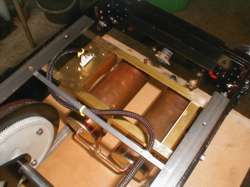
The required suspension springs were deduced from the
weight of the locomotive and the required riding height, which was taken from
the 7.25"G standards and which stipulates a buffer centre height of 5.25"
above the rail. Each part of the locomotive was weighed and listed on a spreadsheet
as sprung weight or un-sprung weight. Suitable 85AH batteries were found and
the specified weight added into the spreadsheet. Allowances were made for any
parts still to be made. The overall 'sprung' weight was estimated as 181lbs
(including batteries). This weight was divided by six to give the weight on
each spring. Parkside Electronics catalogue defines the lbs force per inch of
compression for each of the springs they sell - just the information needed.
The nearest springs available were their No 89 and these were set into the dummy
spring castings so as to give the loco the correct riding height when the batteries
were in place. Rated at 158 lbs/inch each spring would compress 0.191"
and still have 0.209" of travel remaining. However, the total travel of
the spring was such that if the spring was compressed too much the locomotive
wheels would strike the underside of the top plate. Steel 'end caps' were made
to protect the aluminium castings and the plastic axle boxes from the ends of
the springs. These 'end caps' were also designed to limit the amount of spring
compression so that the top and bottom 'end caps' came together and limited
movement. The movement was such that the spring compression was stopped when
the wheels were about 0.125" from the top plate.
 |
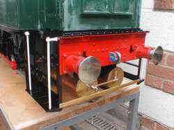
Two lengths of 0.75" Steel Angle have been fitted
the length of the locomotive along the two top edges of the frames. For
good maintainability eight 2BA CSK screws are used to hold the top plate
onto this angle.
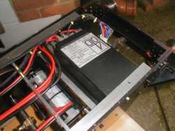
The 4QD Pro-120 Speed Controller is mounted on the
large 4QD heatsink and this is fitted between the frames at the cab end
of the locomotive. Mounted at a shallow angle rather than flat, any water
thrown up by the rear wheels will drip off the heatsink and fall safely
away. The 4QD plastic cover protects the controller from any damage from
above.
|
Two 15-Way 'D' Plugs are used for the electrical
connections to the external speed control box. One plug is mounted on the speed controller heatsink
and this connection is used when controlling the locomotive from the cab
end.
At the front of the locomotive a second plug is mounted on the framework that holds
the twin air tanks. This connection is used when controlling the locomotive
from the radiator end.
The control box wiring is such that with the direction
switch set to 'Forwards' the locomotive will always move in the direction
ahead of the driver (assuming the driver is looking ahead), irrespective
of which way round the locomotive is used.
|
 |
 |
The side window had this large 'sill' on the outside
of the cab which I must admit I had never seen before on the pictures
that I have of a Class 08. This has been removed. The angle on the top of the
fuel tank has been increased and the fuel gauge and access plates removed
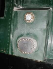
from the body moulding. A small fuel gauge has been turned from brass and polycarbonate
used for the 'glass' and a miniature face put in the gauge. This has been
fitted in the correct place, along with a scaled access plate. Two access
panels were added on the other side of the locomotive, one on the side and
one on the top of the fuel tank.
|
 |
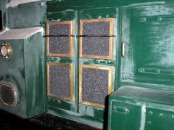
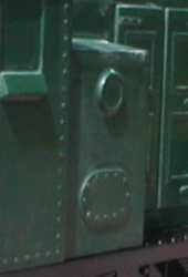
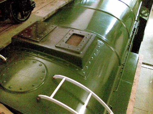
Enhanced Air Filters
replace the original moulded ones |
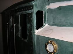
Additional Front Cab windows
where no windows existed in the body shell |
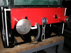
Detailed Front End
Rivets, Crane Lifting Holes, Vacuum Hoses,
Air Tanks, Coupling Protection Plate
Large Footsteps and Handrails |
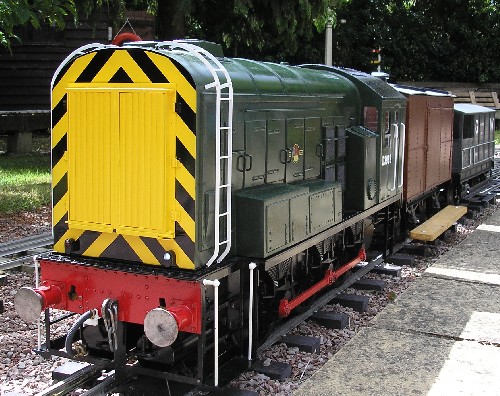 |
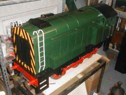
Class 08, July 2006
Working White (ON) and Red lamps.
New Fabricated Radiator Grill
'Wasp' Stripes at front
Roof Ladders
BR Loco Green Colour Scheme |
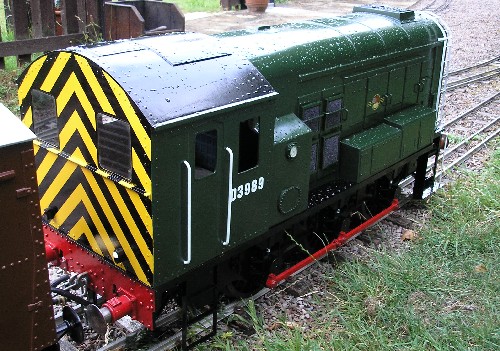 |
Class 08, July 2006
Working White (ON) and Red lamps.
Miniature Fuel Gauge
'Wasp' Stripes at rear
D3989 was a Gloucester (85B) based shunter for many years in the mid 1960's |
 |
|
In 2017 a new digital sound system from Mtroniks Ltd was fitted. This system does sound really good and gives a true 'Start-Up' and 'Shut-Down'' sound effect, in addition to 'acceleration' and a true 'Toot-Toot' whistle rather than the rather oppresive electric horns that most of us have in our locomotives. However, as an 'attention getter' the electric horns are superb. This system differs from the previous sound system in that the digital sounds are not 'time cycled'. The sounds change as soon as one moves the speed controller rather than having to wait for the sound to cycle and change before moving the controller.
If pottering around our club track I fit the sound system with a Class 08 sound chip. However, when passenger hauling I cheat a little and fit a Class 40 sound chip. Sounds great!
For a period I did fit a Smoke Generator (from Magpie Electronics). However, it soon became apparent that it was more trouble then it was worth so it now languishes in a box in the workshop.
|
|
The project is finished.
I have a selection of detailed photographs of Class 08's. Click here if they are of interest. |
 |
|
� |